Electromagnetic InductionaELECTROMAGNETIC INDUCTIONElectromagnetic Induction is defined as the production of emf in a conductor or a coil due to change in magnetic flux linked with the conductor or coil is called electromagnetic induction.Most of the electrical devices which use electric motors and transformers are based on this principle.Faraday's Laws of Electromagnetic Induction
Faraday's performed a series of experiment on electromagnetic induction and the conclusion were as follows:(i). If the magnetic flux linked with a coil changes, then emf is induced in it.ii) The induced emf lasts (exixts) only when there is change in magnetic flux.iii) The amount of induced emf in the coil is directly proportional to the rate of change on magnetic flux.Let, the magnetic flux linked with a coil changes from 𝜙1 to 𝜙2 and induced emf in it is 𝜖 , then from Faraday's Law of electromagnetic induction induced emf ∝ rate of change of flux linkageor, 𝜖 ∝𝜙2-𝜙1
tor, 𝜖=-k 𝜙2-𝜙1
twhere, k is proportionality constant. In SI unit k =1. The negative sing denotes that the emf is induced in such a direction that it opposes the cause due to which it is produced. (Lenz's Law).or, 𝜖=-𝜙2-𝜙1
tIn differential form,𝜖=-d𝜙
dtIf there are N number of turns in a coil, then total emf produced is
𝜖 = - Nd𝜙
dt
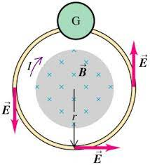
Induced Electric FieldLet us consider a long , thin solenoid of crosssection area A, radius r and number of turns per unit area n as shown in figure.
When current I passes through the solenoid, magnetic field is produced that is B= 𝜇0 n I. We consider all the filed is inside the solenoid and field outside is neglected. let us consider a area vector A in the direction of magnetif field B.Then magnetic flux is written as𝜙 = BA=𝜇0nIAso, induced emf is𝜖=-d𝜙
dt=d
dt(𝜇0 nIA)or, 𝜖=-𝜇0 n A dI
dtHere, a charge moves in the loop, which means there must be an electric field which causes the charge (electron) to move. We know that emf is workdone on moving a charge. The work done is given by line integral of electric field. so,∮E.dl=𝜖So that, ∮E.dl=-d𝜙
dtor, 2𝜋r E= -d𝜙
dtor, E=∣1
2𝜋rd𝜙
dt|Here, E is the magnitude of induced electric field.Lenz's law:
According to Lenz's law, the direction of induced current in a coil is such that it always opposes the cause which produces it. This law follows the law of conservation of energy i.e. Energy neither can be created nor can be destroyed but can change from one form to another. In lenz's law when the magnet is moved towards or away from coil, emf is induced in the coil at the expense of mechanical energy spent by the external agent. Hence in this way mechanical energy is converted to electrical energy. This show the Lenz's law is in accordance with the law of conservation of energy.EMF induced in a straight conductor moving in a uniform magnetic field
Let us consider a straight conductor PQ of length l moving at right angle to a uniform magnetic field B with a velocity v as shown in the figure. Suppose the conductor moves throuth a small distance x in time t. then area swept out (covered) by the conductor = l ⨯ x magnetic flux cut by the conductor , 𝜙= B ⨯ Area swept= B ⨯ l ⨯ x = BlxAccording to Faraday's law of electromagnetic induction, the magnitude of induced emf in the conductor is given bya𝜖=d𝜙
dt=d
dt( Blx)= Bldx
dt
𝜖 = Blv
where , v is the velocity of the rod.IF the conductor moves at an angle 𝜃 with the magnetic field.𝜖 = B v l sin𝜃.Expression for induced e.m.f in a coil rotating in a magnetic field:Let us consider a rectangular coil having area A is placed in a uniform magnetic field B in a such a way that normal to the plane of the coil makes the angle 𝜃 with the magnetic field B as shown in figure
The component of field B at the right angle to the plane of the coil is Bcos𝜃. The flux through the coil is ABcos𝜃. If N be the no. of turns then the flux linkage 𝜙 is given by 𝜙=NABcos𝜃= NABcos𝜔t..............................1If the coil turns, about an axis perpendicular to the field direction with the constant angular velocity 𝜔 then the induce emf in the coil isa𝜖=-d𝜙
dt=-d(NABcos𝜃)
dt=-d(NABcos𝜔t)
dt 𝜖 =BAN 𝜔 sin𝜔t………….2The value of 𝜖 is maximum when 𝜔t = 900, so𝜖0=BAN𝜔, where 𝜖0 is the maximum emf produced.so eqn (2) can be written as𝜖 = 𝜖0sin𝜔t...........................(3)Thus a coil rotating with a constant angular velocity in a uniform magnetic field produces a sinosoidally alternating emf.
If a resistor of resistance R is connected across the coil, the resulting coil will be also a sinosuidal.I =𝜖
R=𝜖0sin𝜔t
Ror, I = I0sin𝜔twhere, I0=𝜖0
R is the maximum current .
AC GeneratorTheory and working of an ac generator:A.C. generator is an electronic mechanic which converts mechanical energy in to electrical energy. It work on the principle of electromagnetic induction i.e. when the coil is rotated in the uniform magnetic field then the emf is developed on the rotating coil.Construction of A.C. generator:
Armature: the rectangular coil (ABCD) consist large no. of turn which wounded the soft iron core is called armature.Strong magnetic field: the rectangular coil ABCD is rotated in the strong magnetic field produce due to magnet N and S.Slip ring: the rectangular coil ABCD are connected with two ring R1 and R2 seperatly. The ring R1and R2 rotated with the rectangular coil ABCD.Brush: the two carbon brush B1 and B2 are fixed and connected with load through which output obtained.WorkingWhen the rectangular coil is roated in the strong magnetic field then the magnetic line of force is cut and flux link changes then according to Faraday’s law of electromagnetic induction, emf is induced in the coil . The current flow out through the brush B1 in one direction while in B2 in other direction i.e. the direction of flow of current are in opposite to each half cycle. Similar process also occurs in another half cycle but in opposite direction as previous. This phenomenon is repeated continuously.Theory: Let the axis of the coil is perpendicular to the magnetic field and coil ABCD is rotated with constant angular velocity ‘ω’ as shown in figure.Let 𝜃 be the angle normal to the coil and magnetic field B at any instant 't' then we have 𝜃=𝜔t………….(1)the component of magnetic field to the plane of the coil is Bcos𝜃 then from equation (1) we have Bcos𝜔tlet A be the area of the coil then the magnetic flux 𝜙=BAcos𝜔tsince the rectangular coil consisting large no. of turn say N then the magnetic flux due to N no. of coil is𝜙=BNAcos𝜔t……….
(2)We know, From Faraday law of electromagnetic InductionaE=-d𝜙
dt=-d(BAN cos𝜔t )
dt=-BNA(-𝜔)sin𝜔tor, E = BAN𝜔 sin 𝜔t......................(3)Let E0=BAN𝜔Then from equation (3) we haveE=E0sin𝜔t……..(4)Dividing the eq. (4) by R we get I=I0sin𝜔t. ..............(5)The equation ( 4) shows that the induced emf E is a sinosuidal wave .
Eddy Current The induced circulating currents produced in a metal itself due to change in magnetic flux linked with the metal are called eddy currents.When a metallic piece is placed in a changing magnetic field, the induced currents are set-up in the metal piece which is eddy currents. The direction of eddy currents is given by Lenz's law.Drawbacks of Eddy Currents1. The production of eddy currents in a metallic block leads to the loss of electrical energy in the form of heat.2. The heat produced due to eddy currents break the insulation used in the electrical machine.3. Eddy currents may cause unwanted dampening effect.Application of Eddy Current1. Induction cooker/Furnace
It is based on the heating effect of eddy currents. The metallic block to be melt is placed in a high frequency changing magnetic field. Strong eddy current is produced in a block. A large amount of heat is produced in the block due to high resistance of the metal. The metallic block melts due to heat. So the induction furnace is used to separate metals from their ores and to make some alloys.Nowadays this tecchnology is being used in induction cooker for domastic use.2. DiathermyEddy currents are used for the localized heating of tissues in the human body which is called diathermy.3. SpeedometerSpeedometer is a device used to measure the instantaneous speed of vehicle. A small magnet is attached to the axle of wheel of the speedometer. Due to the rotation of the magnet magnetic flux linked with the aluminium drum changes and hence eddy currents are produced in it. Higher the eddy current, more deflection is seen the in scale of meter.4. Eddy current damping or dead beat galvanometer As the coil of galvanometer swings in the magnetic field of the instrument, eddy currents are induced in the frame. These eddy currents oppose the motion of the coil and hence the pointer attached to it. The pointer quickly attains the final position without overshooting or oscillating violently. Thus eddy currents reduce the oscillations of the pointer.5. Electromagnetic brakesEddy current breaking can be used to control the speed of electric trains. In order to reduce the speed of train, an electromagnet is turned on that applies its field to the wheels. Large eddy currents are set up which produce the retarding effect.6. Energy metersEnergy meters uses the concept of eddy current to record the consumption of electricity.Self and mutual inductances
When a change current (a.c) passing through a coil then the magnetic flux ɸ linked changes. The changes in the magnetic flux linked causes to induce emf in the coil itself. Therefore the phenomenon by which emf is induction in a coil by passing changing current through itself is called self induction.From faraday's second law of electromagnetic induction, the self inducted emf (𝜖) is proportional to the rate of change of flux 𝜙 linked with the coil i.e.𝜖𝛼 d𝜙
dt………(1)d𝜙
dt is also propotional to the dI
dt i.e. d𝜙
dt 𝛼 dI
dt…..(2)from equation (1) and (2) we have 𝜖𝛼dI
dt or, 𝜖=-LdI
dt where L is proportionality constant called coefficient of self induction. Or, L=-e
dI
dtif, -dI
dt=1L=𝜖Hence, Inductance (L) is also define as the emf induced for unit rate of decrease of current through itself.Mutual Induction
The induction of an emf in the coil due to the flow of current in the neighboring coil is called mutual induction. If S1 and S2 are the two coils place near to each other, the changing current I1 is set up in the coil S1,then the magnetic field around it also changes due to which flux linked with S2 is also changing if 𝜙2 is the flux linked with S2 then, then, the magnetic flux inside the solenoid S1is given byB1= 𝜇0n1I1=𝜇0N1
lI1 where, n1=N1
lAs, B=𝜙
Athe magnetic flux linked with each turns of solenoid S1is = B1Aand the total flux solenoid S2 is = N2B1Aie. 𝜙2=N2𝜇0N1
lI1Aor, 𝜙2= 𝜇0N1N2A
l I1or, 𝜙2= M12I1Where, M12=𝜇0N1N2
lA is the mutual inductance, when current fluctates in solenoid S1 and emf is induced in solenoid S2.Simillarly, when current fluctated in solenoid S2thenM21=𝜇0N1N2
lA so, M12=M21=Mso,
M =𝜇0N1N2
lA
Energy Stored in a InductorConsider an inductor of inductance L having initially zero current. It is assumed that an inductor has zero resistance so that there is no dissipation of energy with in inductor. Let I be the current at any instant of time so that dI/dt is the rate of change of current. Here current is increasing. The voltage between the terminals a and bof the inductor at this instant is Vab=Ldi
dt and the rate P at which energy is being delivered to the inductor is given byP=vabI=LdI
dt I =LIdI
dtThe energy supplied to the inductor in small amount of time is small which is written asa
dU
=Pdt (∵ P =dU
dt)
=LIdI
dtdt
dU
= LI dI
To obtain total amount of energy stored in the inductor, we have to integrate it from 0 to I.∴ Total energy stored in an inductor, a
i.e U
=I∫0L.I.dI
or, U
=L[I2
2]I0=1
2LI2
U=1
2LI2
Construction and working of a transformer:Transformers is a device used to convert high volt, low current AC into low volt high current AC or vice versa.
The transformer which converts high voltage AC into low voltage is called step down transformers. The transformers which converts low voltage AC into high voltage is called step up transformers. Transformer is based on the principle of mutual induction.When a magnetic flux is linked with a coil changes emf is induced in the nearby coil. It consists of two coild, primary and secondary of insulated copper wire on the laminated soft iron core. The soft iron core consists of thin strips of iron coated with vanish to insulated from each other and put together to form a single. The primary coil is connected with the source of AC and the secondary is connected with the load.When the current is passed through the primary coil, magnetic flux linked with the coil changes and emf is induced in the coil.If 𝜙 is the flux linked with the primary coil and Ep is itself induction then the primary voltage. Ep is given by:Ep=-NPd𝜙
dt… (i) Where, Np is the number of turns in the primary coil. If there is no loss of flux then the rate of flux linked with the secondary coil will be same.Then the induced emf is secondary coil,Or, ES=NS⋅d𝜙
dt… (ii)Where, NS is the number of turns in secondary coil. Dividing equation (i) and (ii), we get,Or, EP
Es=Np
Ns = kWhere, Np
Ns= k, is called transformer ratioIf NP/NS>1 then EP>ES and the transformer is step down.If NP/NS then ES>EP and the transformers in step up.If Lp and Ls is the coefficient of self - induction of primary and secondary coil respectively.For an ideal transformer, there is no any power loss.ie. Input power = Output power.Then,a
IpEp=ISES
Or, Ep
Es=Is
Ip.
Hence, the output voltage is increased, the output current will decrease and vice - versa. Therefore, for a long distance transmission line, high voltage is used. If the secondary voltage is high then current will be below and hence the energy loss (I2Rt) due to resistance of wire is low.Cause of Energy loss in Practical Transformer1. Copper LossesEnergy lost in windings of the transformer is known as copper loss. When current flows through copper wires, there is loss in power. This can be reduced by using thick wires for windings.2. Flux lossesIn the actual transformer, the coupling between primary and secondary coil is not perfect. So certain amount of electrical energy supplied to the primary coil is wasted.3. Iron lossesa)Eddy current losses:When a changing magnetic flux links with the iron core of the transformer, eddy currents are set-up. These eddy currents in the iron core produce heat which leads to wastage of energy. This can be reduced by using laminated core.b. Hysteresis lossesWhen alternating current passes through the primary coil of the transformer, the iron core of the transformer is magnetized and demagnetized over a complete cycle. Some energy is lost during magnetizing and demagnetizing the iron core. The energy loss in a complete cycle is equal to the area of the hysteresis loop. This can be minimized by using the suitable material having narrow hysteresis loop for the core of a transformer.4. Losses due to vibration of core
A transformer produces humming noise due to magnetostriction effect. Some electrical energy is lost in the form of mechanical energy to produce vibration in the core.
Some New Questions
In a coil of resistance 10Ω the induced current developed by changing magnetic flux through it, is shown in the figure as a function of time. The magnitude of change in flux through the coil in Weber is: