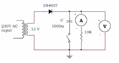
AIM: To observe waveform at the output of half wave rectifier with and without
filter capacitor. To measure DC voltage, DC current, ripple factor with and without
filter capacitor
Appratus Required
- Breadboard
- Ammemeter, Voltmeter
- Step Down Transformer
- Diode 1N4007
- Resistor 10K
- Capacitor 1000μF
- Oscilloscope
Theory:
One of the very important applications of diode is in DC power supply as a rectifier
to convert AC into DC. DC Power supply is the important element of any electronic
equipment. This is because it provides power to energize all electronic circuits like
oscillators, amplifiers and so on. In electronic equipments, D.C. power supply is
must. For example, we can’t think of television, computer, radio, telephone, mobile
as well as measuring instruments like CRO, multi-meter etc. without DC power
supply. The reliability and performance of the electronic system proper design of
power supply is necessary. The first block of DC power supply is rectifier. Rectifier
may be defined as an electronic device used to convert ac voltage or current into
unidirectional voltage or current. Essentially rectifier needs unidirectional device.
Diode has unidirectional property hence suitable for rectifier. Rectifier broadly
divided into two categories: Half wave rectifier and full wave rectifier. In this
experiment, you will construct half wave rectifier.
Working principle of half wave rectifier:
In half wave rectifier only half cycle of applied AC voltage is used. Another half
cycle of AC voltage (negative cycle) is not used. Only one diode is used which
conducts during positive cycle. The circuit diagram of half wave rectifier without
capacitor is shown in the following figure. During positive half cycle of the input
voltage anode of the diode is positive compared with the cathode. Diode is in
forward bias and current passes through the diode and positive cycle develops
across the load resistance RL. During negative half cycle of input voltage, anode is
negative with respected to cathode and diode is in reverse bias. No current passes
through the diode hence output voltage is zero.
[1] Without filter capacitor
AC Input voltage (rms) Vrms= ___________
DC output voltage VDC = ___________
DC current: IDC =______________
AC output voltage (Ripple voltage) Vr: __________
Ripple factor: (Vr/VDC) = ______________
[2] With filter capacitor
AC Input voltage (rms) Vrms= ___________
DC output voltage VDC = ___________
DC current: IDC =______________
AC output voltage (Ripple voltage) Vr: __________
Ripple factor: (Vr/VDC) = ______________

