Monday, October 25, 2021

Electric Circuit

electric-circuit
Kirchhoff's Law First Law (Kirchhoff's Current Law) It states that in any network of the conductors, the algebraic sum of currents meeting at a point is zero. In the other hand it is simply means that the total current leaving a junction is equal to the total current entering that junction. Explanation: let us consider 5 currents meeting t a junction P of the network as shown in figure
Let us adopt the following sign conversions for determine the algebraic sign of different currents. All current entering the junction would be taken as positive whereas those leaving it would be taken as negative. So, I1 and I4 would be taken as positive whereas I2, I3 and I5 would be taken as negative. Using Kirchhoff’s of current law we have,I1+(-I2)+(-I3)+I4 +(-I5)=0Or, ∑I=0Also, taking the negative of the expression on one side and positive sign on other side,I1+ I4 = I2+I 3+I5so we can write,total Incoming current = total outgoing currentIin=Iout. Kirchhoff’s Second law (Kirchhofff's Volatage Law): It states that the algebraic sum of all IR drops and EMF in any close loop of network is zero.∑IR =∑EMF=0
Explanation: let us consider a complex circuit given below to find the current at the various part of the circuit we use Kirchhoff’s law. Let us consider the direction of emf and current flow in anticlockwise direction is taken as positive and clockwise direction as negative. According to second law of Kirchhoff’s, we have∑IR =∑EMF For the closed loop AFCBA, (+E1)+(-E2) = (+I1)R1+(-I2)R2 Or, E1-E2 = I1R 2-I1R2 .........................(1) Similarly for closed loop FEDCF E2 –E3 = I2R2-I3 R3 ..........................(ii) Also from first law of Kirchhoff’s, we also have ∑I=0 ans from sign convention we have I3=I2 +I1 ........................................(iii)Solving these equations, (i), (ii) and (iii), we can calculated the required value of pd, current or resistance. Wheat stone bridge’s principle: It is an electronic device which measure accurate resistance of the conductor. it measure unknown resistance with the help of known resistance. Let P, Q and R are three known resistance and X be the unknown resistance are connected in quadrilateral closed electric circuit and the two junction of the quadrilateral are connected with battery and the remain two junction are connected galvanometer and the deflection was not shown by the galvanometer. These conditions called balance condition.
At this condition, Ig= 0 at this condition P
Q
= X
R
Determination for the balanced condition for the bridge: To determine the balance condition the arrangement are shown in figure above. Let us consider the 4 resistance in are arrange in quadrilateral from when it is connected with battery then current is divided into two part i.e I1 and I3 passes through the resistance P and Q. similarly I2 and I4 are passes through resistance X and R respectively. From second law of Kirchhoff’s law for the closed loop ABDA we have I1P + IgRg - I2X = 0 or, I1P + IgRg = I2X ..................(i) Similar for closed loop BDCB we have, IgRg + I4 R - I3Q = 0or, I3Q= IgRg + I4R ......................(ii) Again from first law of Kirchhoff’s at point D I2 + Ig = I4 ..................(iii) Similarly at B we have I1 = Ig +I3 .................(iv) Now at balance condition Ig=0 and no current passes through the galvanometer then above equation (i), (ii), (iii), and (iv) become: I1P = I2X ……………..(v) I3 Q = I4R ………(vi) I2 =I4 ………(vii) I 1 = I3 ………………(viii) Dividing eq. (v) by (6) we have I1P
I3Q
=I2X
I4R
Substituting the values of I1 and I2 from equn (vii) and (viii). I1P
I1Q
=I2X
I2R
or, P
Q
=X
R
This is the expression for the balance condition of the Wheatstone bridge. Meter Bridge Meter bridge is a electric device which is used to measure the unknown resistance. It works on the principle wheat stone bridge circuit.
It consists of 1 meter long uniform wire, A resistance box and unknown resistance are connected in two gaps of meter bridge. A galvanometer is connected along with jockey which is slided over the wire to find the nul deflection. A source is connected across the bridge to maintain current in the circuit. According to the wheat stone bridge principle, P
Q
=R
X
or, Resistance of length AB
Resistance of length BC
=R
X
where, AB= and BC=(100-l)then we have, p and Q(100-)So,
(100-𝜃)
=R
X
X=(100-ℓ)R
l
If the unknown resistance is at the left gap and resistance box is at right gap of the meterbridge then. x=l
(100-1)
R
So, the value of X can be calculated for different value of R. P.O BoxPost oflice box is an instrument that works on the Wheat stone baidge principle. It is so called because, this instrument was used to find the resistance of broken telegraph wires in the post office. Potentiometer is electrical sensitive device which is use for following purpose a. To measure emf and internal resistance of cell. b. To compare emf of two cells and p.d between two point of circuit and c. To measure current and resistance accurately of given circuit. P.O Box is a compact forn of Wheat stone bridge more specially a resistance box in which the resistances with in the box serve as three arms of Wheat stone bridge and value of unknown resistance can be found by inserting it in the fourth arm. This box consists of two ratio arms AB and BC which serve as P and Q of the wheat stone bridge and a third long arm CD which serves as the known resistance. An unknown resistance is inserted between A and D whose value is to be determined. Each ratio arm consists of three resistance marked 10Ω,100Ω and 1000Ω inside the box where as the known resistance arm has the resistances ranging from 1 to 5000Ω inside the box. A source of emf is connected betwecn A and C which is connected to C when the key K1 is pressed. A galvanometer is connected between D and B is connected to B by a key K2. while noting the readings, battery key (K1) is pressed first and then Ki is pressed in order to avoid inductive effects in the galvanometer coil.Measurement Procedure
Let an unknown resistance X be connected between A and D.At first, 10Ω resistors are plucked out of each ratio arms P and Q so that, the ratio P
Q
=1
1
Now, the known resistors from arm CD are plucked out so as to observe the deflection in the galvanometer. By changing the value of known resistance gradually, the deflection in the galvanometer changes it direction. If the galvanometer shows left (say) deflection for and right deflection for resistor taken out of CD, then, we say that the resistance lies between and .In second step, the ratio of arms P and Q are maintained at P:Q=10:100. In this case the value of X now nust increase 10 times and hence. We check its resistance correctly betweerı 30Ω and 40Ω by plucking suitable resistors. In this case also, we try to find opposite detlections of galvanometer for two consecutive value of R. It, the galvanometer shows opposite detlection for 36Ω and 37Ω then. we say, the resistance lies between 3.6Ω to 3.7Ω. Sometimes, we may get a null deflection for particular value say 36Ω. In such case we can directly say the value of unknown resistance is 3.6Ω. Finally the ratio P:Q is maintained at 10:1000 by plucking 1000Ω key from Q. The same procedure is repeated as this time by plucking the rcsistance key bctween 360Ω and 370Ω . If a null deflection is obtained for certain value of R, say 361Ω then we say the resistance of the wire is 361Ω. If the null deflection is not obtained and still opposite deflections exist, then we adopt following method to calculate exact value of X, Suppose, for, R=361Ω galvanometer deflects by 2 divisions left and for R =362Ω galvanometer detlects by 1 division right. Total deflection of galvanometer for change in resistance =2+1=3 divisions. Here, 3 division corresponds to 1Ω resistanceor, 1 division corresponds to 1
3
Ω
resistance
or, 2 division corresponds to 2
3
Ω
resistance. Therefore, the value of resistance R required for null deflection =(361+2
3
)Ω=361.66Ω
Thus, the salue of urknown resistance fron wheat stone bridge principle is, P
Q
=x
R
.
a
or, X=P
O
×R
or, X=10
1000
×361.66
X=3.616Ω
In this way, we can determined, the value unknown resistance using P.O Box.

Potentiometer


original image
A potentiometer is an electric device used to measure the emf and internal resistance of a cell, to compare emf of two cells and a potential difference between two points in an electric circuit. It can also be employed to measure the current and resistance in a circuit accurately.
It consists of a uniform wire of manganin or constantan of length usually , kept stretched between copper stripes fixed on a wooden board by the side of a metre scale. The wire is divided into ten segments each of length. These segments are joined in series through metal strips between points and . A steady current is maintained in the wire by a constant source of emf , called driver cell, that is connected between and through a rheostat. A jockey is slided over the potentiometer wire which makes contact with the wire and cell.
let I be the current passing through the potentiometer wire . In a segment AC of the wire, let be the potential difference across it.
Then,
where is the resistance of this segment.
If 1 is the length of this segment, its resistance is
where to the resistivity of the material of the wire and its cross section area.
From and , we have
Since and I are all constant,
then
is a proportionality constant and we can write
The potential difference across any portion of the potential of the potentiometer wire is directly proportional to the length of that portion provided the current is uniform.

Application of Potentiometer
A potentiometer basically measures the potential difference between two points.
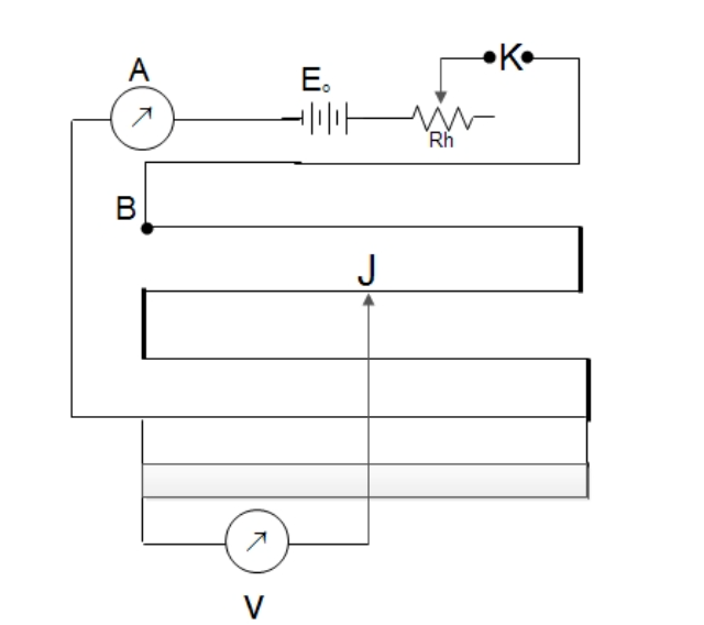
1. Determination of Internal Resistance of a Cell
original image
A cell of emf E whose internal resistance is to be determined is connected in the potentiometer circuit. The positive terminal of is connected to where positive terminal of the driving cell is connected and the negative terminal to a galvanometer. A resistance box is connected parallel to the cell through a key . a steady current is passed through the wire by the driving cell.

Initiallly the key is open and the emf of the cell is balanced in the potentiometer wire. Suppose the balanced point obtained at and let be the length of wire AD. Then is balanced by p.d. across AD. So,
From the principle of potentiometer
Now, a known resistance is provided by R.B. and the key is closed. A current l' will pass in the closed circuit of and . then a terminal p.d., is obtained across the cell which is again balanced by the p.d. in the potentiometer wire. Let ' be the point at which the null deflection is obtained and p.d. across be '. So,
If is the length of this portion ' of the wire, from the principle of potentiometer
Dividing equation by equation , we get
and the terminal p.d.,
Substituting these values in equation (iii), we get
As and are known, the internal resistance of the cell can be determined.
2) Comparison of emfs of two Cells and Determination of emf of a Cell
original image
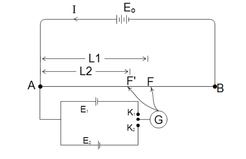
Two cells whose emfs and are to be compared are connected in the potentiometer circuit as shown in the figure. The driving cell of emf maintains a steady current in the circuit of the potentiometer wire . The positive terminals of and are connected at where positive terminal of is connected and the negative terminals to the two-way key. A galvanometer is connected between the key and the jockey that slides over the wire. must be greater than and .
One of the cells say is connected in the circuit by closing of the two-way key and disconnected by making open. The jockey is slide along the wire to find the null point. When the jockey is placed at near on the wire, the length of portion is small and p.d., in it is small. As the emf is greater than , the current will flow through the galvanometer, G in the direction of and the galvanometer is deflected in the left direction.
When the jockey is placed at near , the p.d., across portion AD will be greater than and the current will flow through, in opposite direction of So, the galvanometer shows deflection in right direction. This work confirms that the circuit is correct and by trail and error method, a point says is found at which G shows null deflection. At this condition, p.d. across is equal to emf, and in the galvanometer coil. So, whole emf is balanced by the p.d. in the length of the wire. So, at the balanced condition,
From the principle of potentiometer,
So
...........(i)
Similar work is repeated for the next cell, . Then we will get
..........(ii)
Dividing . (i) by Eq. (ii), we get
Sincel 4 and are measured in the potentiometer wire, can be determined.
If the emf of one cell, say is known, the emf of the other cell can be determined as .
Super Conductor SuperconductorA superconductor is an element or metallic alloy which, when cooled below a certain threshold temperature, the material dramatically loses all electrical resistance. In principle, superconductors can allow electrical current to flow without any energy loss (although, in practice, an ideal superconductor is very hard to produce). This type of current is called a supercurrent.
Type of SuperconductorType I (Soft): These are usually made of pure metal. When it is cooled below its critical temperature it exhibits zero resistivity and displays perfect diamagnetism. This means that the magnetic fields cannot penetrate it while it is in the superconducting state.Type II (Hard): These superconductors are usually alloys and which looses magnetization gradually rather than sudden are termed as type II or hard superconductors.Applications of Super ConductorThe applications of superconductors include the following. These are used in generators, particle accelerators, transportation, electric motors, computing, medical, power transmission, etc.Superconductors mainly used for creating powerful electromagnets in MRI scanners. This conductor is used to transmit power for long distancesUsed in memory or storage elements.Super conductors are used in laboratories for ligh level research works.It is used in thin film devices.Perfect ConductorA perfect conductor is an electrical conductor with no resistivity. n a perfect conductor, electric charges are free to move without any resistance to their motion. Metals provide a reasonable approximation to perfect conductors, although, of course, in a real metal a small amount of resistance to motion is present. A perfect conductor is an idealized material exhibiting infinite electrical conductivity or, equivalently, zero resistivity. While perfect electrical conductors do not exist in nature, the concept is a useful model when electrical resistance is negligible compared to other effects. One example is electrical circuit diagrams, in which we assume that the connecting wires have no resistance. Difference between Superconductor and percect conductorSuperconductivity is a phenomenon occurring in real life, while perfect conductivity is an assumption made to ease the calculations.Perfect Conductors can have any temperature, but superconductors only exist below the critical temperature of the material.In perfect conductor, the magnetic flux within the perfect conductor must be constant with time. Any external field applied to a perfect conductor will have no effect on its internal field configuration while in superconductor magnetic flux is expelled out, ie there is no any mangetic field. ShuntShunt is a low resistance connected in parallel with resistance of a galvanometer while converting galvanometer into ammeter.Conversion of Galvanometer into Ammeter Let us consider the resistance of the galvanometer is G, the maximum current measured by the ammeter is I, and the maximum current measure by the galvanometer by passing through it is Ig, then the current passes through the small resistance i.e. shunt S is (I-Ig) as shown in figure
Since the resistance of the galvanometer and shunt are in parallel then a/c to the property of parallel combination we have, Potential difference across shunt = Potential difference across galvanometer (I-Ig)S = IgG Or, S = IgG
I -Ig
……………..(i)
Hence equation (i) gives the value of shunt to convert an galvanometer into a ammeter with range 0 - I ampere Since the S and G resistance are in parallel then the effective resistance of ammeter (RA) is given by 1
RA
=1
G
+1
S
or, RA=GS
G+S
This show the resistance of ammeter (RA) very smaller (lower) then that of shunt S. So, when it is connected ammeter is connected in series in circuit then there is no effect the on current passing through the circuit.Conservation of galvanometer in to Voltmeter:A voltmeter is a device used to measure potential difference between two points in a circuit. It is connected across two points between which the potential difference is to be measured. By connecting a voltmeter in a circuit must not change the current and hence the potential difference in the circuit, a voltmeter should have very high resistance, ideally infinite resistance. Such p.d. measuring device can be made by connecting a very high resistance in series with a galvanometer.
Let G be the resistance of galvanometer and Ig current producing the maximum deflection in the galvanometer. To measure the maximum voltage, V by the voltmeter, the high resistance R is connected in series. So, V = Ig (R + G) Or, IgR = V – IgG. Or, R = V
Ig
-G
This equation gives the value of resistance R, which has connected in series to the galvanometer, and this connection converts the galvanometer into voltmeter of range 0 – V volts. The effective resistance of the voltmeter RV = R + G. Since, R is high, the resistance of the voltmeter RV is high and it will not draw much current from the circuit.Ohmmeter
An ohmmeter is an arrangement which used for measuring resistance. It consists of a meter a resistor and a source connected in series as shown in a figure. The resistance R to be measured is connected between the terminals. The series R is variable, it is adjusted as that when terminals and are short-circuited (i.e. when R→ ), the metre deflects full-scale. When nothing is connected to terminals, so that the circuit is open (i.e. when R=0 ), there is no current and no deflection. For any value of R , the meter deflection depends on the value of R, and the metre scale can be calibrated to read the resistance, so this scale reads backward compared to the scale showing the current. Joule's laws of heating of electric currentHeat produced in a conductor due to the flow of current is(a) directly proportional to the square of current i.e. HI2. ............(i)(b) directly proportional to the resistance of conductor i.e. HR. ..........(ii)(c) directly proportional to the time for which current is passed through the conductor i.e. Ht………. (iii)Combining above all equations, HI2RtH=I2Rt
J
, where J is constant called Joule's mechanical equivalent of heat.
In SI units J = 1. so
H=IRt
Experimental Verification of Joule's Law of Heating
Experimental arrangement for verification of Joule's law of heating is shown in the figure below, where a caloimeter filled with water is taken and resistance wire is immersed in water. A thermometer immersed in the calorimeter records the temperature of water. Here, the rheostat (Rh) changes the current in the circuit. As we pass current by closing the key (k), the resistance (R) becomes hot and this heat energy is absorbed by the water and the calorimeter. The heat absorbed by the calorimeter and the water is given by H=mcsc𝛥𝜃+mwSw𝛥𝜃or, H=(mcSc+mwSw)𝛥𝜃Here, mcSc+mwSw= Constant H𝛥𝜃Now different magnitude of current is passed through the circuit with the help of theostat for equal time and then heat will be produced in the wire and temperature of water rises. It is found that the ratio of heat produced (rise in temp.) and the square of current is always constant.i.e. H1
I 12
=H2
I22
=H3
I23
HI2 ......................(i)
The experiment is repeated again for different length of resistance wire keeping current and time on which current passed constant, it is found that amount of heat produced ie. rise in temperature is directly proportional to the length of the wire used. As the resistance of the wire is proportional to the length.i.e. HR .....................(ii)
Again the experiment is repeated so that same amount of current is passed through the circuit for different interval of time keeping resistance constant. Then it is found that heat produced is directly proportional to the time for which the current is passed ie. H 𝛼 t ..............(iii)
Combining above all equations, H 𝛼 I2Rtor, H=I2RtThis verifies the Joule's law of heating.

No comments:

Post a Comment

Featured Post

Meiosis

Meiosis Cell Division Prophase-I occurs over a long duration and involves several complicated changes in meiotic cell division. It is import...